
GPIO
What is GPIO?
GPIO stands for General-Purpose Input/Output.
It's a configurable digital connection on a microcontroller or processor that allows software to interact with external hardware.
For example, you can use GPIO to:
- Read a push button.
- Turn an LED on or off.
- Control a relay.
- Read a digital sensor's output.
- Communicate with external hardware using custom digital signaling.
how a GPIO pin is physically built inside a silicon chip.
A GPIO pin is not just a wire connected to the CPU. It is connected to a small electronic circuit fabricated inside the silicon.
At a simplified level, the circuit contains:
- MOSFET transistors that drive the output voltage.
- An input-sensing circuit that detects the pin voltage.
- Control circuitry that decides whether the pin is an input or output.
- Configuration and data storage elements.
Let's first understand the two transistors that make a typical digital output work.
The two-transistor circuit: push-pull output
A typical GPIO output uses CMOS technology: a PMOS transistor and an NMOS transistor.
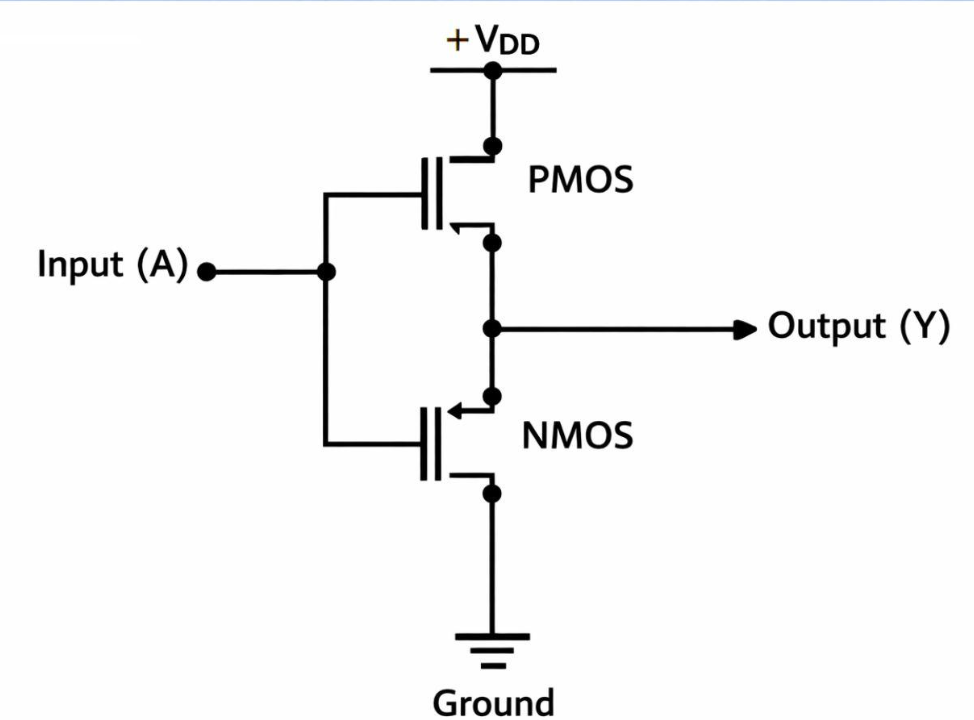
Think of a MOSFET as an electrically controlled switch. A voltage applied to its gate controls whether a conductive path forms between its other two terminals.
- PMOS: In a typical GPIO output stage, it connects the output toward the positive supply, VDD.
- NMOS: It connects the output toward ground, GND.
The two transistors are controlled so that normally only one is on at a time.
Case A: Software writes 1
PMOS ON, NMOS OFF
VDD = 3.3 V ---> PMOS: conducting ---> GPIO pin ≈ 3.3 V
The output pin is driven toward VDD. If an LED circuit is connected between this pin and ground, current can flow through the LED and its resistor.
Case B: Software writes 0
PMOS OFF, NMOS ON
VDD = 3.3 V ---> PMOS: OFF ---> GND = 0 V
The NMOS pulls the output toward ground.
This is the fundamental principle behind a GPIO output. The circuit switches the pin between two voltage rails; the CPU itself does not directly generate the pin voltage.
For detailed PMOS and NMOS refer(TODO)
How does GPIO read an input?
The input circuit works differently.
Imagine connecting a button to a GPIO pin. When the button is pressed, the voltage on the pin changes.
Inside the chip, the pin is connected to an input buffer. Its transistors sense the voltage and convert it into a digital logic level.
External pin voltage(For example, 0 V or 3.3 V) ---> Input buffer(Transistor-based voltage-sensing circuit) ---> Digital result(Logic 0 or logic 1)
The chip has specified input-voltage thresholds. For example, a sufficiently low voltage is interpreted as LOW and a sufficiently high voltage as HIGH. The region between the guaranteed thresholds is not a reliable logic level.
Many GPIOs use a Schmitt-trigger input buffer, which has different switching thresholds for rising and falling voltages. This helps reject small amounts of electrical noise.
Notice the difference:
- Output mode: transistors drive the pin voltage.
- Input mode: transistors sense the pin voltage.
The internal transistor circuit connects to a metal pad, which connects to a package pin or solder ball. That package connection ultimately connects to a PCB trace.
Between the internal circuit and the outside world, the chip generally also includes protection structures against electrostatic discharge (ESD).
CPU/bus → GPIO control and storage → transistor output driver or input buffer → silicon pad → package terminal → PCB trace → external circuit.
NOTE: The exact architecture varies by chip, but the principle is common.
how a register actually control a transistor?
The hardware path looks approximately like this:
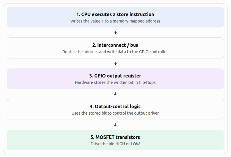
Let's understand the important parts.
What physically stores the register value?
A typical hardware register is built from digital storage elements called flip-flops.A flip-flop is a circuit made from transistors that retains a binary state. When the appropriate write or clock event occurs, it captures the input bit and holds that state until it is changed or reset.
For example:
- Write 1 → the register stores a logic HIGH.
- Write 0 → the register stores a logic LOW.
The register is not usually a tiny memory chip. It is a small digital circuit fabricated inside the GPIO controller.
How does the register control the transistor?
Suppose the output register stores 1, and the pin is configured as an output.
The register's output is an electrical logic signal. It connects to the GPIO controller's output logic, which controls the gates of the output transistors.
For a simplified push-pull output:
| Output register | PMOS | NMOS | Pin |
|---|---|---|---|
| 1 | ON | OFF | HIGH |
| 0 | OFF | ON | LOW |
The register's value doesn't flow through the transistor to the external circuit as data. Instead, the value acts as a control signal that determines which transistor conducts.
The transistors then establish the voltage on the pin using the chip's power supply.
One subtle point: the output-enable and pin-multiplexer configuration also matter. A stored 1 alone does not guarantee that the physical pin becomes HIGH if the output driver is disabled or the pin is assigned to another peripheral.
But how does the CPU reach that register?
The GPIO register usually has a memory-mapped address.
NOTE: There is no software continuously checking the register and then deciding what to do. Once the register is written, its hardware output remains at the corresponding logic level, and the connected circuit responds electrically. This is why a single register write can change a physical pin without the CPU executing a loop.
©2023-2024 rculock.com